| The RA 742 |
| The RA 742 |
|
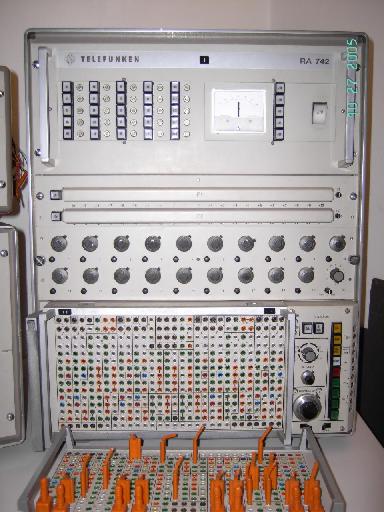
The RA742 is the latest of TELEFUNKEN's very successfull line of transistorized table top analog computers. All in all the system has 25 chopper stabilized operational amplifiers with an open loop gain of 10^8 (!), four multipliers, two user settable diode based function generators, 20 coefficient potentiometers and a centralized removable patch panel. The term "table top" may seem a bit euphemistic since the system weighs 105 kg. The overall system consists of three drawers (which are not 19 inch - TELEFUNKEN used a proprietary system with drawers being about 21 inches wide):
|
|
|
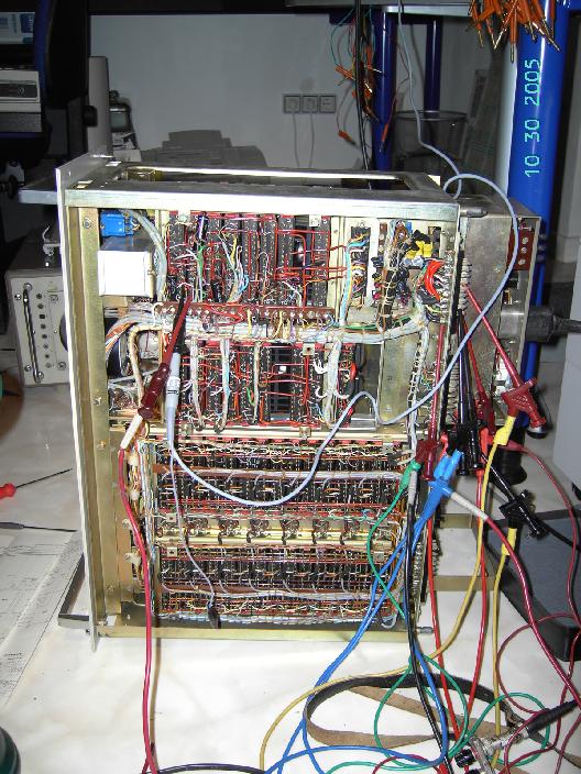
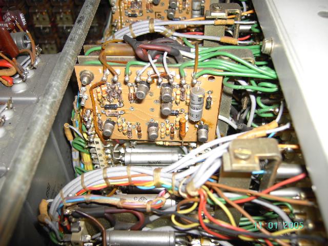
Power supplies and operational amplifiers: The pictures below show the power supply drawer which contains most of the operational amplifiers of the system, too. The power supply fills the right half of the drawer and is one of the most complex power supplies I have ever seen. When I got the system it was not operational due to a failing power supply for the machine units of +/- 10 V. This high precision power supply is a double rail power supply, i.e. the + 10 V path depends on the - 10 V path and vice versa. The trick of the circuit is that the regulator is artificially destabilized at power up by a small relais which I removed since I wanted to debug the circuitry without any interfering signals. Removing this relais was quite stupid as I realized many hours later since the power supply can not work with out it. I alread had found and fixed the bug but I did not realize this due to the missing startup relais. The picture on the right shows the power supply during debugging. When running this drawer out of the rack one has to short a couple of pins on its rear since the power supplies have voltage sense inputs and the power supply will expect an external reference if a certain bridge it missing on its rear connectors. All in all the power supply is a bit difficult to understand and repair. |
|

|
|
|
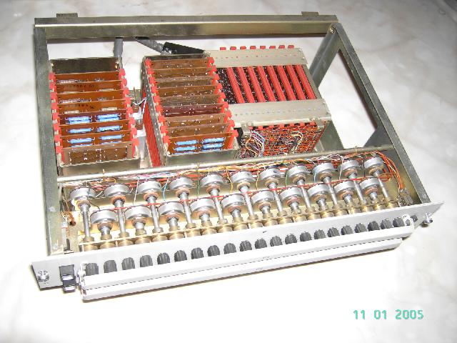
Function generators and coefficient potentiometers: The picture on the left below shows the top of the middle drawer of the analog computer. Located at the front are the setup potentiometers of the two diode function generators. The knobs are connected to the potentiometers by means of 5:1-gears to facilitate the setup procedure. Behind the potentiometers are the cards for these two function generators - in the right half of the drawer are the fixed function cards for sine and cosine terms. The picture on the right shows the bottom view of this drawer. |
|
|
|
|
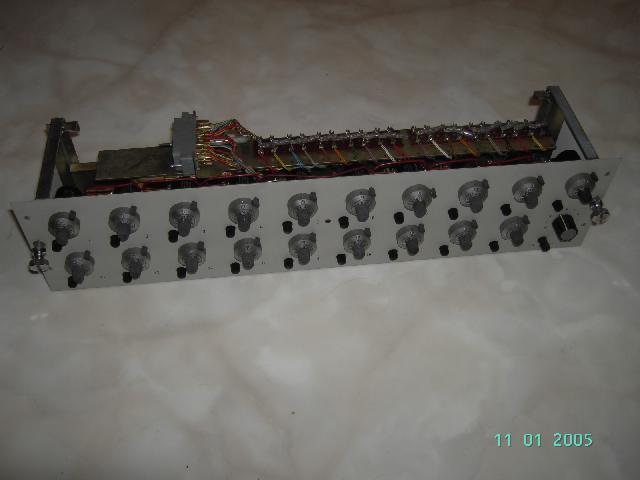
The picture below on the left shows the drawer containing the 20 coefficient potentiometers. These are 10 turn precision potentiometers. Older versions of TELEFUNKEN analog computers used miniature fuses rated for 5 mA to protect these precious potentiometers from be fried by a erroneous program setup. This last model uses small bulbs connected between the slider of each potentiometer and the output available at the removable patch panel. These protective bulbs can be clearly seen in the picture on the right. |
|
|

|
|
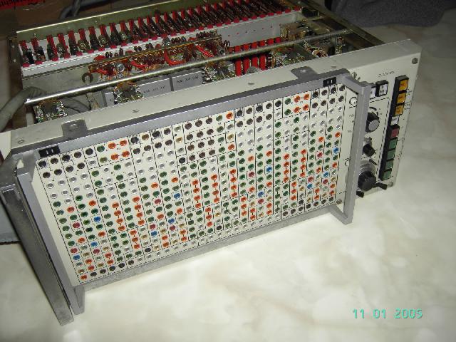
The patch and control panel drawer: The picture below shows the front of the bottom drawer of the RA742 analog computer. The most prominent feature is the removable patch panel. On the right of the panel is the rather small control panel where the switches for setting the desired mode of computing, setting the system timer, etc. are located. |
|
|
|
|
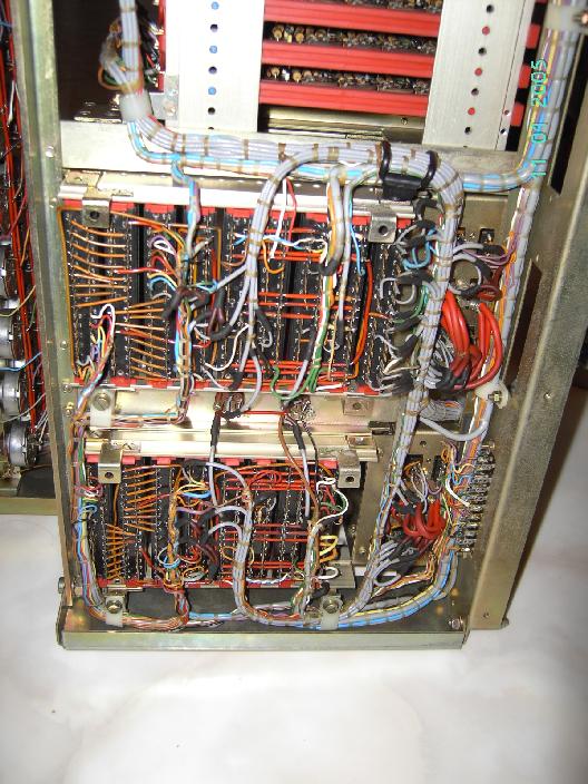
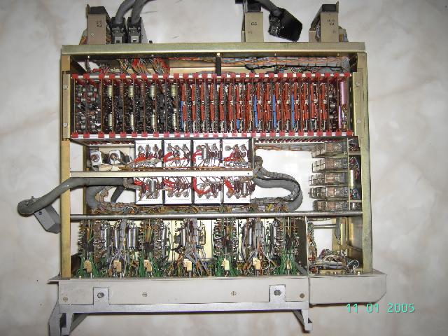
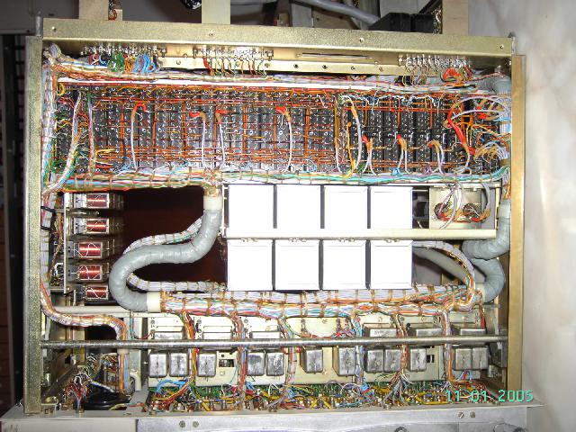
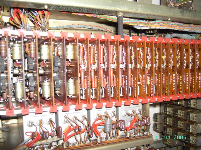
The picture below left shows the top view of this drawer: From top to bottom the units contained herein are: Operational amplfiers for the four parabola multipliers and the parabola function generator cards. In the middle are the three times eight integrator capacitors - on the right are the mode control relais. At the bottom of the picture the patch panel and the integrator control electronics can be seen. The picture on the right shows the bottom view of the drawer. |
|
|
|
|
The picture on the left shows the integrator capacitors in more detail. The picture on the right shows some of the printed circuit cards holding the operational amplifiers and the parabola function generators for the four multipliers. |
|

|
|
|
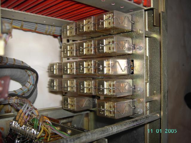
The picture on the left shows the mode control relais in more detail - the complete control logic of the computer is implemented using relais. The integrator control is in contrast to this purely electronic employing solid state switches for setting the integrator modes. |
|
|
|
|
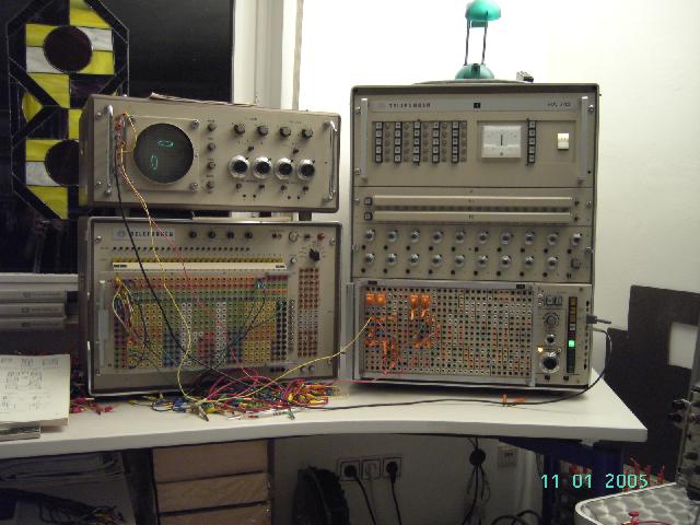
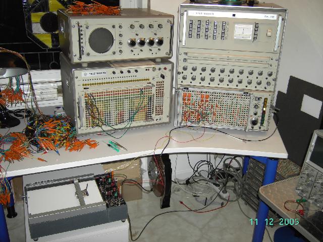
Two actual calculations: The pictures below show the two first calculations perfomed on this truly wonderful analog computer after its power supply was successfully repaired. On the left two ellipses are displayed on the OMS800 dual beam oscilloscope (an AVI-file of this calculation can be seen here). The picture on the right shows the system setup with an ink pen plotter - an AVI-file showing the plotting of a nice curve can be seen here (the file is quite large - about 12 MB - so the download can take a considerable amount of time!). |
|
|
|
|
Documentation:
|
|
| 26-JAN-2006, 26-JAN-2008 |