Hybrid controller
|
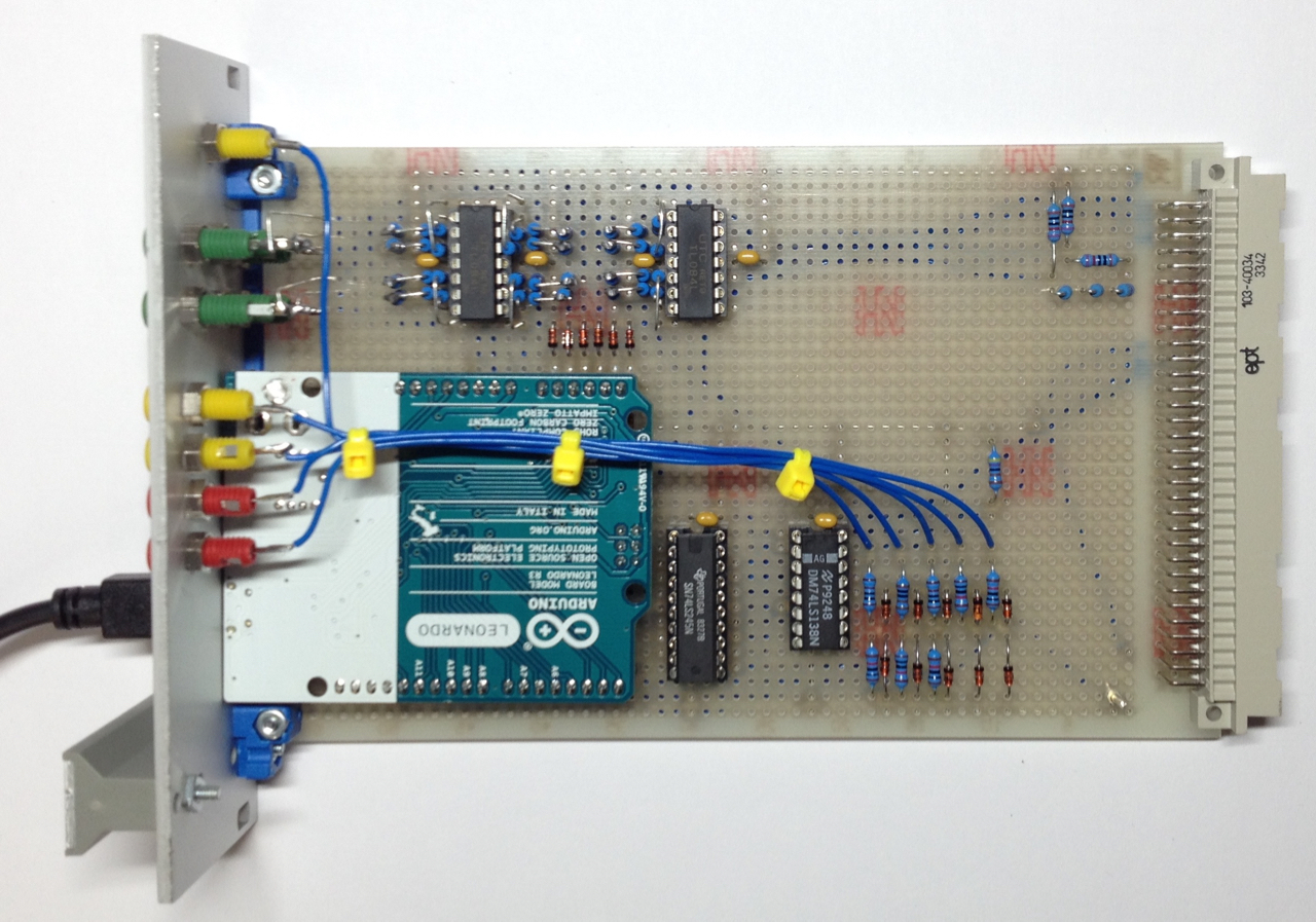
The only thing that is (might be :-) ) better than an analog computer is a hybrid computer, a system consisting of an analog computer and a stored-program computer (aka digital computer). In such a system each subsystem performs the task it is ideally suited for: The analog computer takes care of simulating a dynamic system while the digital computer may, for example, supply initial conditions for the analog part of the simulation, generate functions of more than one variable, perform complex decisions etc. Although many larger analog computers already features a very basic digital control unit, a true hybrid computer requires an interface between analog and digital computer capable of not only controlling the operating mode of the analog computer from the its digital counterpart but also transferring data from one side to the other. As I had some days off, I decided to build a simple yet powerful hybrid controller which can be used with almost every electronic analog computer. The picture above shows it in its current state. It has the following characteristics:
Currently missing are digital potentiometers but these will be added shortly and will greatly amplify the capability of the hybrid controller (called HyCon in the following). In its current state, the hybrid controller expects a TTL-signal from the analog computer to denote an overflow condition and generates TTL-signals to control the integrator modes of the analog computer. If you intend to use this controller for a "classic" analog computer, make sure that you adapt the output drivers as well as the input stages of the controller to reflect the requirements of the analog computer being controlled. As one can see, it is based on an Arduino Leonardo board which I had at hand. The four additional integrated circuits are a 74LS245 to drive the digital control lines and LEDs, a 74LS138 to decode the current state of operation of the analog computer, and two quad operational amplifiers that act as level shifters for the analog inputs of the Arduino board. The schematic of this hybrid controller is quite simple: 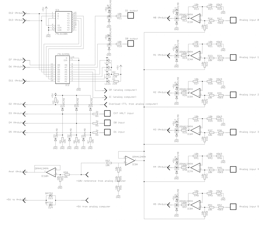
The six operational amplifiers on the right side are level shifters. These map a signal from the analog computer with a range of +/-15 V to the permissible range of 0-5V as required by the AD-converter of the Arduino. I decided to map the full +/-15 V range instead of mapping the typical +/-10 V range to be on the safe side when it comes to overloads. This reduces the 10 bit resolution of the AD-converter to a tad over 9 bits, still enough for a simple hybrid interface like this. These level shifters require an offset which is derived from the +10 V reference from the analog computer by means of a voltage divider with an impedance converter (IC9A). IC10A acts as impedance converter for another voltage divider which derives a precise +5 V reference based on the analog computer's +10 V reference. Its output feeds the Aref-input of the Arduino board. The source code for the Arduino board can be found here. The communication between the controller and the digital computer takes place over a simulated serial line interface. The hybrid controller can be controlled manually via a simple terminal emulator and supports the following commands:
a           Disable halt-on-overflow
A           Enable halt-on-overflow
b           Disable external halt
B           Enable external halt
c{ms}\\n     Set OP time for repetitive/single operation
C{ms}\\n     Set IC time for repetitive/single operation
d{01}       Clear digital output 0/1
D{01}       Set digital output 0/1
e           Start repetitive operation
E           Start single IC/OP-cycle
h           Halt
i           Initial condition
o           Operate
r           Read analog inputs
R           Read digital inputs
s           Print status
t           Print elapsed OP-time
?           Print Help
Since manual control is quite point less on a hybrid computer, I wrote a simple Perl module that allows true hybrid computing. The documentation of the module can be found here while its source code is here. Now that it is possible to control the analog computer from a digital computer, a little demonstration is due: The following problem is quite simple - a projectile is fired from a given height y_0 at a given and fixed elevation angle alpha. Its initial velocity is variable and determines the impact point of the projectile. The task is now to determine a suitable initial velocity v_0 to reach a target point. The problem is mathematically readily described by the following two equations: 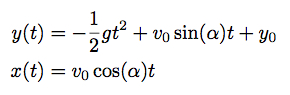

So far, so good - the problem is that the hybrid controller as of now has no way to generate an analog output voltage or control a digital potentiometer which could both be used to derive a suitable v_0 input signal to the above circuit. But there are two digital output lines which can be "repurposed" for that: One output controls an electronic switch that yields an output value of +1 or -1 and feeds an integrator which is switched between OP and HALT by means of the second digital output. :-) The required circuit is shown below: 
Now, a short control program is necessary to orchestrate the simulation. Based on HyCon.pm it looks like this:
use strict;
use warnings;

use File::Basename;
use Time::HiRes qw(usleep);
use HyCon;

$| = 1; # Force autoflush to display the difference between target and shell

sub vary_v0 # MIC = +1, MOP = D0, polarity control = D1
{
    my ($ac, $value) = @_;
    $ac->digital_output(1, $value > 0 ? 0 : 1); # Select polarity
    $ac->digital_output(0, 0);                  # Set integrator to OP
    usleep(abs($value) * 1e6);                  # Wait a moment
    $ac->digital_output(0, 1);                  # Switch bach to HALT
}

(my $config_filename = basename($0)) =~ s/\.pl$//;
my $ac = HyCon->new("$config_filename.yml");

$ac->digital_output(0, 1); # Set v0-Integrator to HALT

$ac->disable_ovl_halt();
$ac->enable_ext_halt();

my ($ic_time, $op_time) = (10, 10);  # Milliseconds, prepare repetitive run
$ac->set_ic_time($ic_time);
$ac->set_op_time($op_time);

# Perform one run, HALT when the shell hits the ground, use difference between
# target and shell position to improve v0 for the next run
while (1)
{
    $ac->single_run();
    usleep(($ic_time + $op_time + 1) * 1000);
    my $response = $ac->get_response(); # Fetch the "External halt!"-response
    my $result = $ac->read_analog();
    printf "\r%+0.4f", $result->[0];
    vary_v0($ac, -$result->[0] / 1000); # Much too slow, but nice demonstration
}
The function At the end of each such run, the miss distance of the projectile is read from the first analog input of the hybrid controller and used to update the initial velocity for the next run. The divisor 1000 is a bit large and results in a sluggish response of the system but makes for a pretty nice demonstration. The following video shows the operation of the overall hybrid simulation. The first seven seconds are run with the v_0-integrator's time constant set to 1 - the overall response to a moving target is accordingly slow. After about seven seconds, the time constant of that particular integrator is switched to 10, resulting in a much more agile response. Reducing the divisor in the second before last line of the code above has pretty much the same effect. 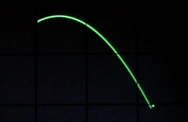
The overall setup used for this particular simulation looks like this: 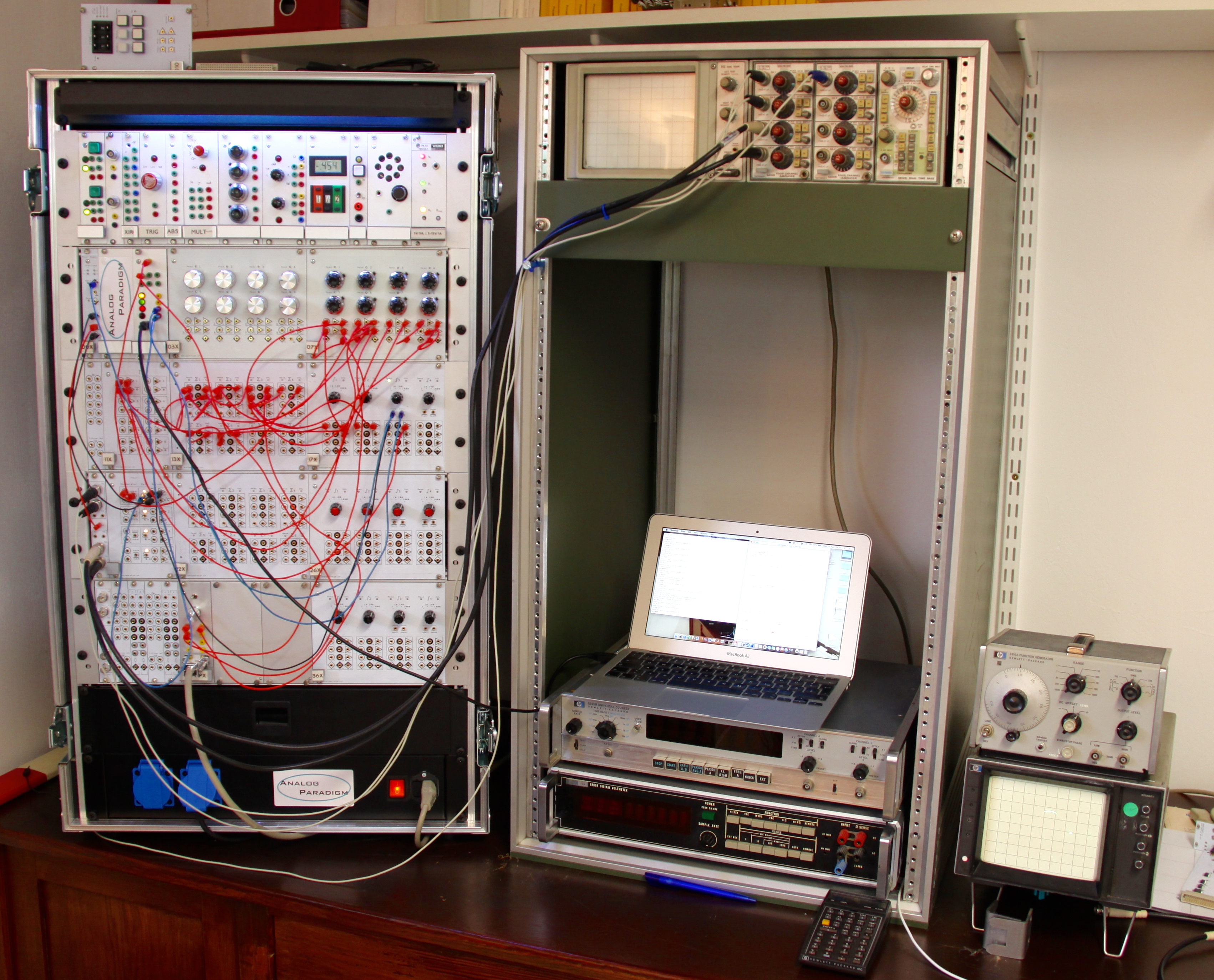
|
|
|
10-AUG-2016, ulmann@analogmuseum.org |