Restoration of an OMS 811 Dual Beam Oscilloscope |
|
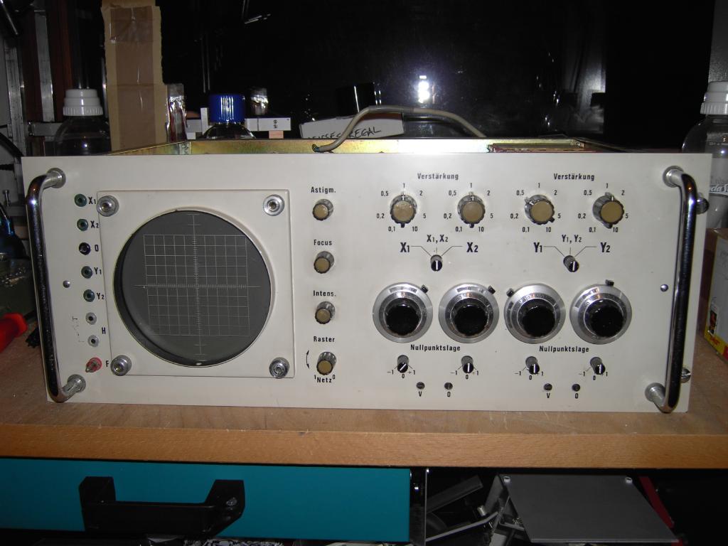
The picture above shows a TELEFUNKEN OMS 811 dual beam oscilloscope which was normally used in conjunction with TELEFUNKEN's wonderful transistorized precision analog computers like the large scale RA 800(H) but also with the table top analog computers RA 741 or the more modern RA 742. I bought the oscilloscope shown above about two weeks ago for approximately 60 EUR, an absolute bargain! A first inspection made it clear that the oscilloscope had been modified and was at least not in "mint condition" (to be honest, I did not expect anything else thinking of the low price of this wonderful device): Two of the precision knobs for the beam position control potentiometers had loosened - fixing this was simple after finding a suitable tool fitting into the tiny screws of the knobs. 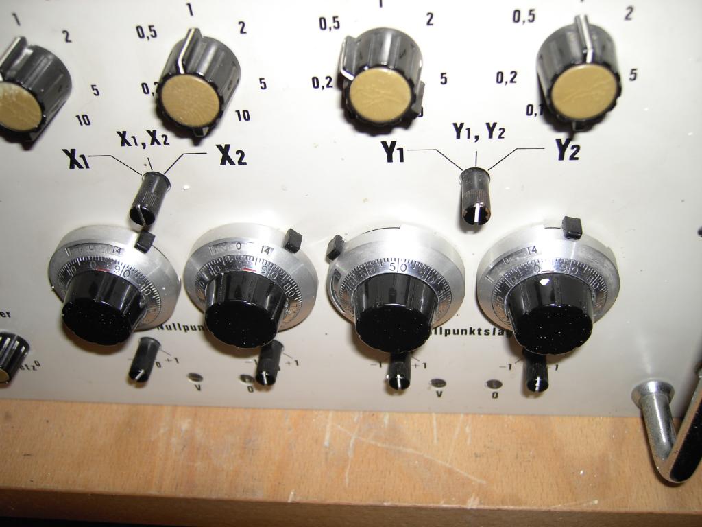
That was simple. :-) Now, what is that cinch plug doing in the lower left corner of the oscilloscope? Normally there should be a special connector looking like a 4 mm banana jack which is compatible with the flash light cables from (ancient) photo cameras. Normally this input was used to start a computation at the very moment of taking a photography from the oscilloscope screen. Since I do not need this feature I decided to remove the (horrible) cinch plug and replace it with a simple 4 mm banana jack. Shorting this input to ground would now trigger a computer run. 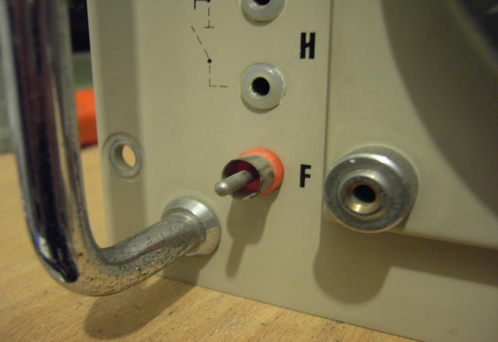
Another problem was the broken fuse holder shown below. Although a fairly simple device it was hard to replace since its mounting bracket can not be removed from the oscilloscope's frame, so there is not much room to work in. 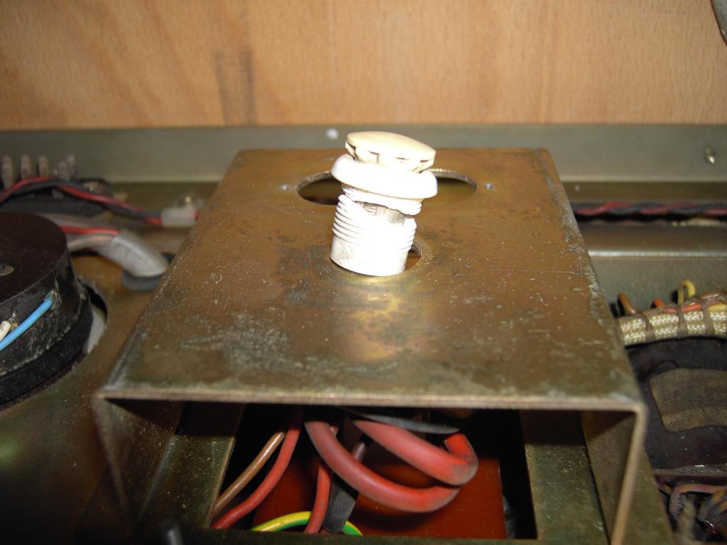
The next thing I noticed was that the old line in connector of the oscilloscope was missing and had been replaced by a fixed line cord without a pull relief which was connected to the device by a simple luster terminal. In addition to this the leads of the cables had been tinned which is not a good idea since tin under pressure (of the screws of the luster terminal) acts like a fluid which will eventually result in a bad connection: 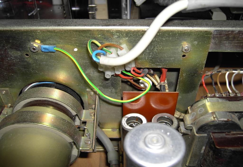
Clearly this had to be changed - unfortunately I had no spare power jack from the 1960s, so I decided to stay with the fixed power cord which I soldered to the transformer inputs. In addition to this I built a simple pull relief which fits into the space formerly occupied by the power connector (please note the alumunium plate covering the hole). The picture below also shows the new (old :-) ) fuse holder replacing the broken one. 
The next thing to fix was the acceleration high voltage connector shown below - it had become loose because the high voltage transformer was only secured with one screw instead of two which caused the whole transformer and rectifier module to break free during the postal transport. The problem was that the connector had been under severe stress and was deformed giving no reliable contact. I had to disassemble the connector and tighten it before reconnecting it to the high voltage output terminal. 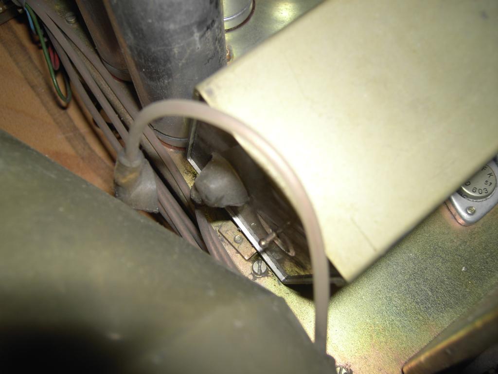
The picture below shows the high voltage transformer and rectifier module. Fortunately it did not damage any other parts of the oscilloscope, so the only thing I had to do was flattening one of its mounting brackets and finding a suitable screw for the second bracket. 
After fixing these (minor) problems it was time to switch the oscilloscope on for the first time after its restoration (never attempt something like this without a isolating transformer and always keep in mind that oscilloscopes employing electron tubes have lethal voltages present at many places!). After the tubes had come to life (there are, in fact, three tubes in this device - the display tube, a DN 13-14, and two double triodes used to control the deflection voltage of +/-600 V!) it became clear that the oscilloscope was far from being working properly. The beam was incredibly bright and the intensity switch did not have much effect on this, so I immediately switched the oscilloscope off to avoid damage to the display tube (in fact there were already some blind spots when I got the instrument, so I assume that its prior owner had tried to operate the instrument with this erroneous beam intensity for a prolonged amount of time) and started thinking - what would cause such a behaviour? The beam was so bright that not only the two expected dots (X1/Y1 and X2/Y2) were visible but also the movement of the electron beam between the switch over from one input pair to the other! The following picture shows the oscilloscope on my work bench setup for debugging: 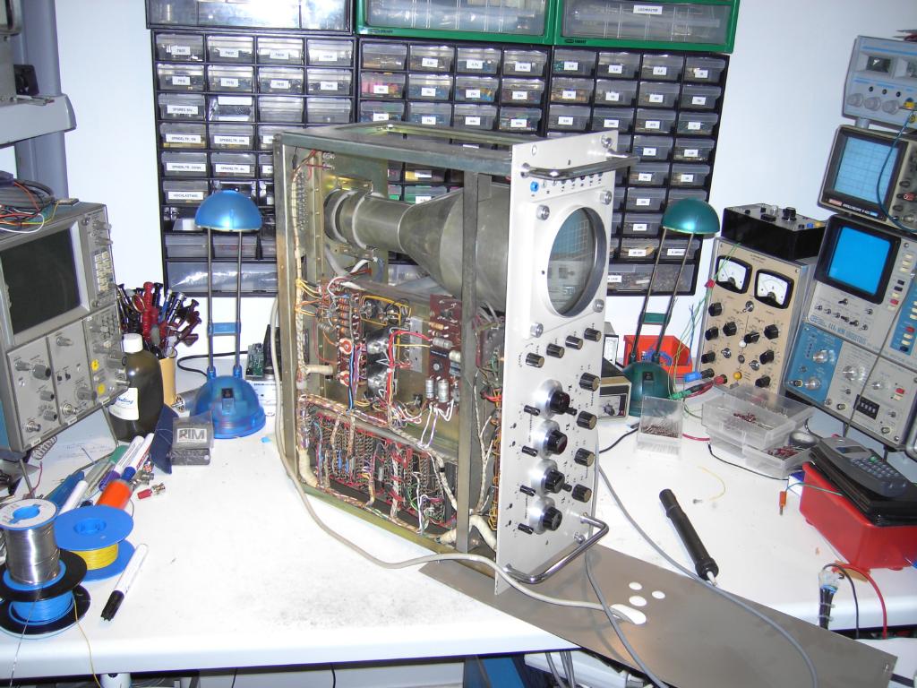
The first thing one will normally do is to check all power supply voltages - in this case I wired all outputs I wanted to check to a rotary switch allowing me to scan the output lines quickly to avoid a burn in of the electron beam. It turned out that all voltages (+/-15 V, +55 V - this is used for the blanking circuitry, +/- 600 V - used for the deflection circuitry) were well within their specifications, so at least there was no problem with the power supply itself. So I started to have a look at the blanking circuitry which is a bit tricky in the OMS 811. There are two circuits working in an antagonistic way:
The beam intensification circuitry seemed to me being the most probable candidate for causing this behaviour. After redrawing part of the schematic the circuit became a bit clearer to me. The idea is to inject a DC voltage at the Wehnelt input of the display tube by bypassing the intensity potentiometer with a BC 107 transistor. Since this transistor is at a potential of about -1800 V its base input is decoupled by an optocoupler which in turn is driven by a PNP transistor connected to the intensification logic. The intensification logic turned out to be working correctly - the primary PNP transistor was switched on and off correctly depending on the backplane input from the analog computer or depending on the selection of only one input pair. The infrared LED of the optocouple seemed to be working also. Unfortunately I could not measure on the other side of the optocouple since all remaining circuitry was on a potential of -1800 V and I do not have high voltage probes for my Tektronix oscilloscopes. So I decided to unsolder one side of the "hot" side of the optocouple to measure the resulting effect - if the beam intensity would diminish this would prove that the circuitry built around the BC 107 transistor was working correctly. The picture below shows the optocouple with one of the high voltage leads desoldered: 
After switching the oscilloscope on for another time it became clear that the problem was caused by the optocouple itself! The beam intensity was now perfectly normal and could be varied with the intensity potentiometer as expected, so the high voltage side was working properly. Since the intensity logic was working correctly, too, the only possible source of the error was the optocoupler. A quick check with an Ohm meter showed that the photodiode was shorted which in turn caused the BC 107 to conduct, which injected the high DC voltage into the Wehnelt input, resulting in the observed excessive beam intensity. Unfortunately I had no replacement part for this ancient optocoupler, so I decided to leave it in place and desolder one of its photodiode's leads thus deactivating the intensification circuitry as a whole. This is far from being elegant, but since I do not plan to perform analog computations at a repetition cycle of 100 us or less and I do not plan to take screen shots with a photo camera with roll film, I will not miss this feature at all. After fixing this bug (too bad that the CRT already had some dead spots when I received the oscilloscope - if you have a DN 13-14 for sale, please let me know! :-) ) I connected the instrument with two sine generators to display some lissajous figures as a final test. During this I realized that one of the position control switches did not work - after disassembling the switch and cleaning the contacts and reassembling, the oscilloscope worked just perfectly. |
| 14-DEC-2006, 26-JAN-2008 |