|

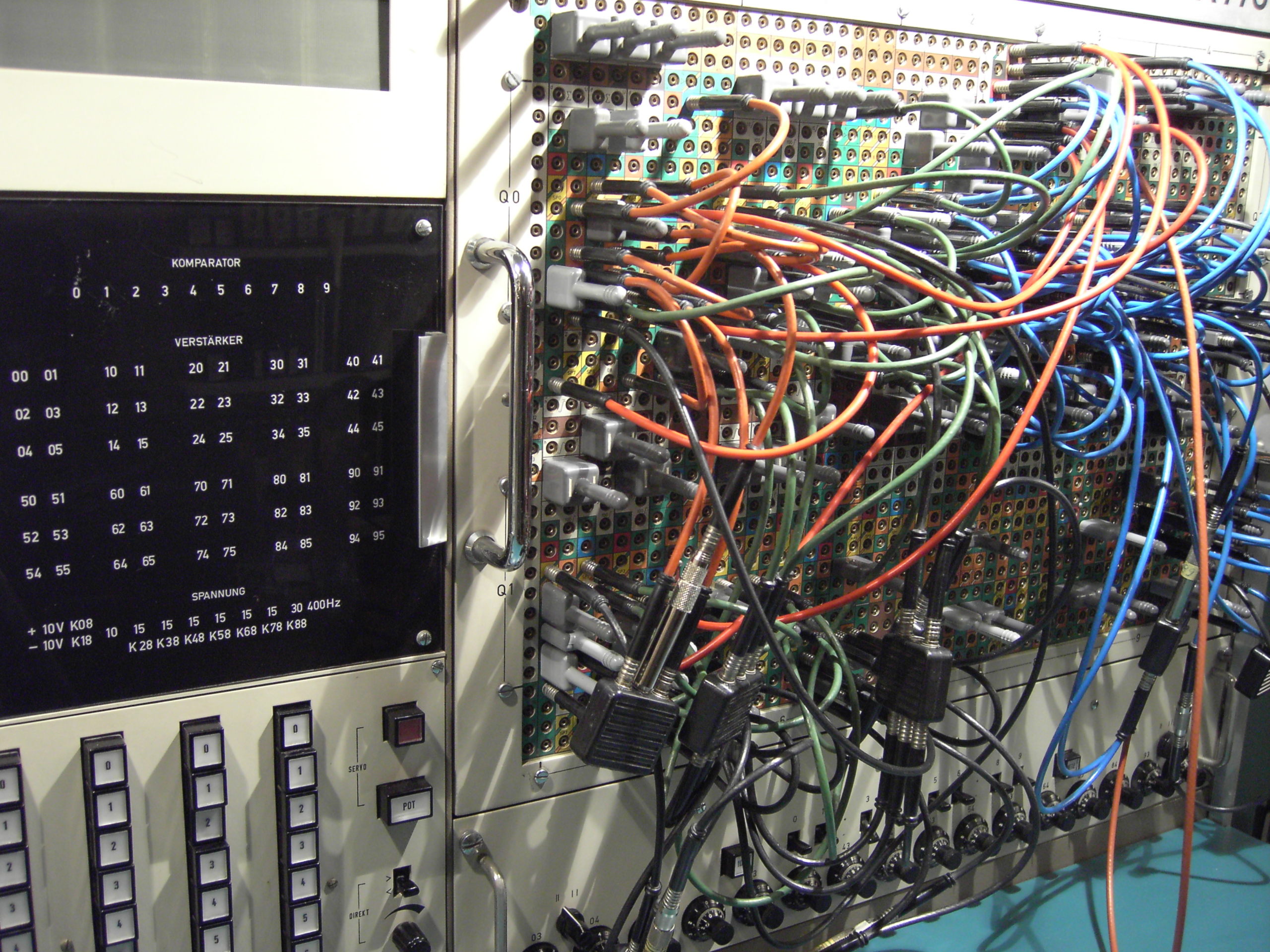
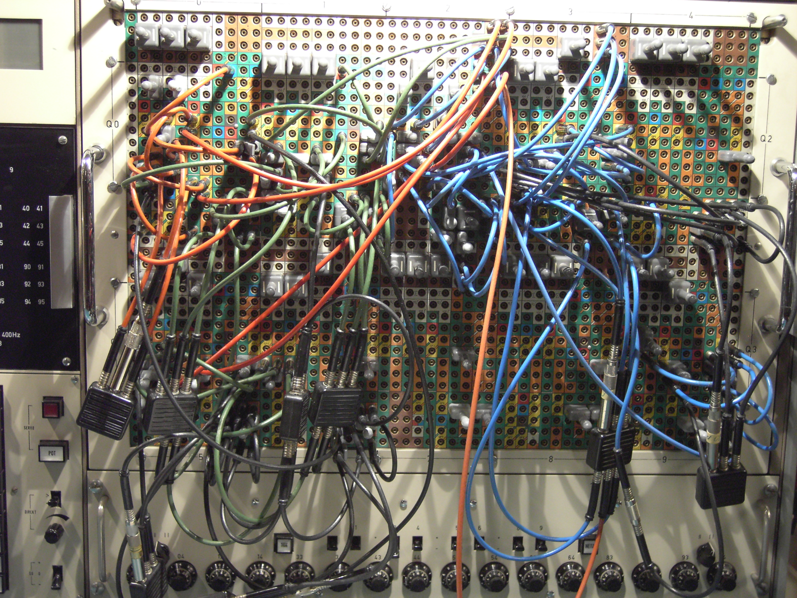
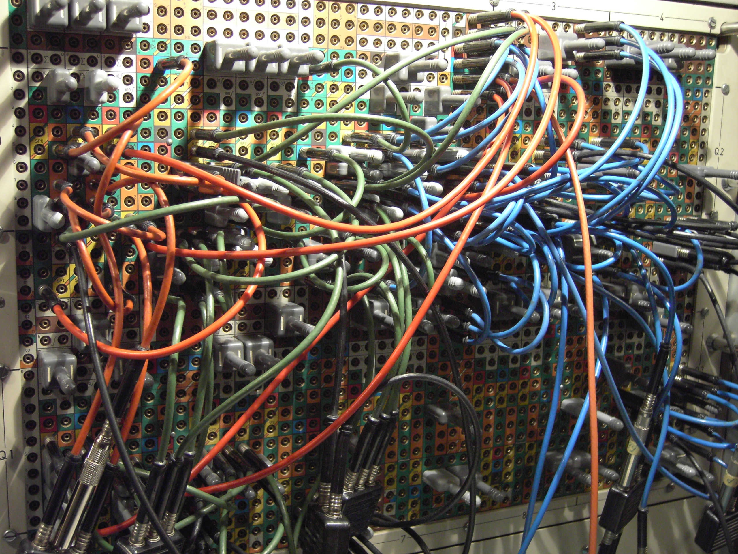
About a week ago I stumbled over an old Telefunken application note describing the display of a so called Joukowski airofoil with lines of flow around based on conformal transformations. This reminded me of a rather interesting section in the book "Incompressible Aerodynamics" by Bryan Thwaites (Dover Books, 1987) which covers the basic techniques of the application of conformal transformations in the area of aerodynamics. I decided that the generation of a Joukowski airofoil with its surrounding lines of airflow would be ideally suited for my wonderful Telefunken RA 770 analog computer. The picture above gives an impression of the analog part of the complete Joukowski program (it requires a little bit of digital logic for the iteration process which will be shown below). The basic idea of a Joukowski airofoil is rather simple - it is based on a certain conformal transformation of a circle. If you are not interested in the shape of the particular airofoil but in the lines of air flow around this profile the very same transformation may be applied to another set of input data. In this case one would generate lines of flow around an infinite rotating cylinder. These lines of flow will be transformed with the conformal transformation which led to the Joukowski airofoil thus generating the lines of airflow around this particular profile. The four pictures below give some impressions of the program. The color of the cables denote different parts of the program. The red coded subprogram on the left hand side of the patch panel generates the circle which serves as the basis of the Joukowski airofoil. The blue program part generates the lines of flow around the infinite rotating cylinder while the green part implements the actual conformal transformation (the black subcircuits are dividers used in the conformal transformation as well as in the cylinder airflow subprogram). |
|

|
|
|
|
|
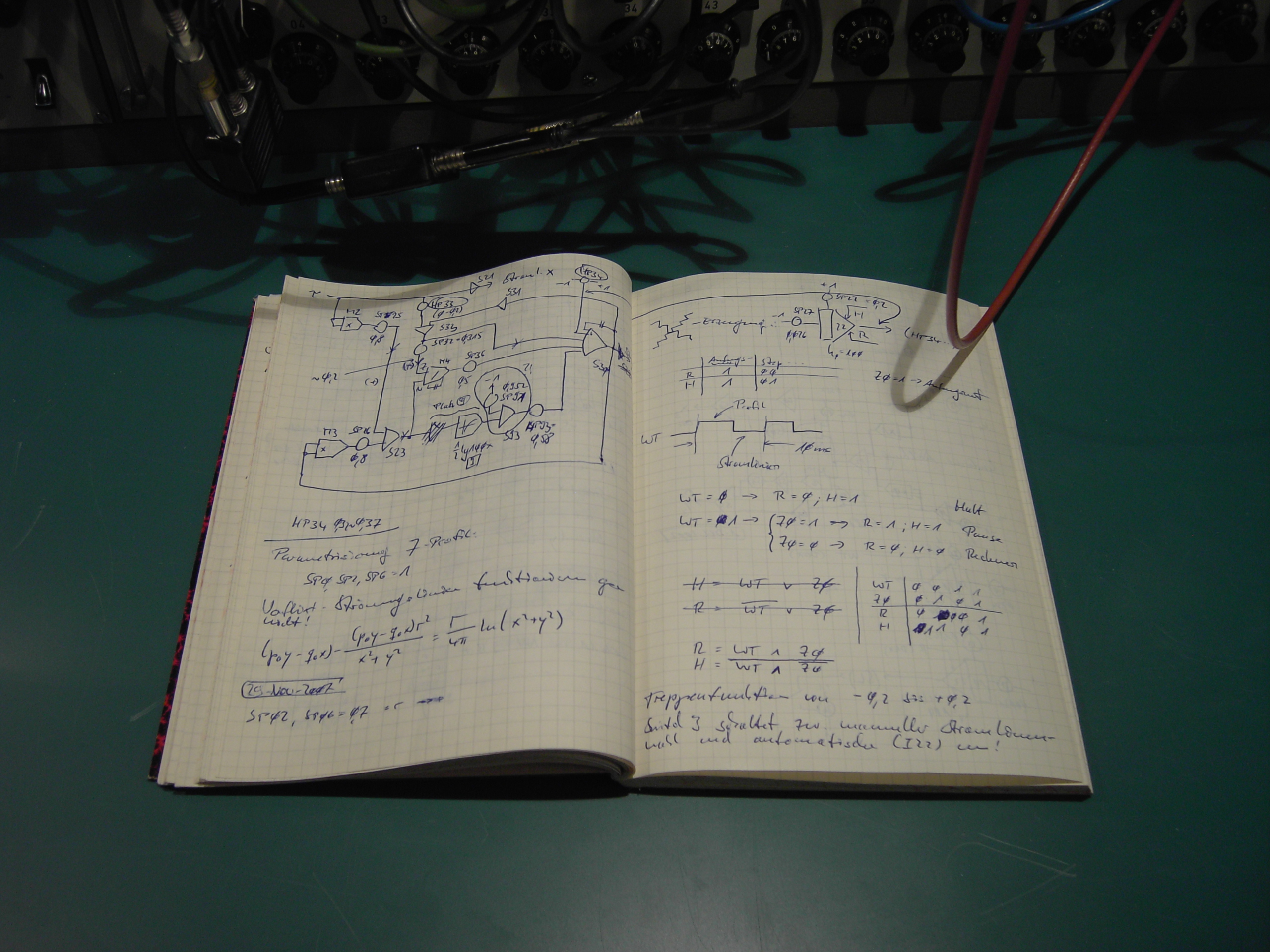
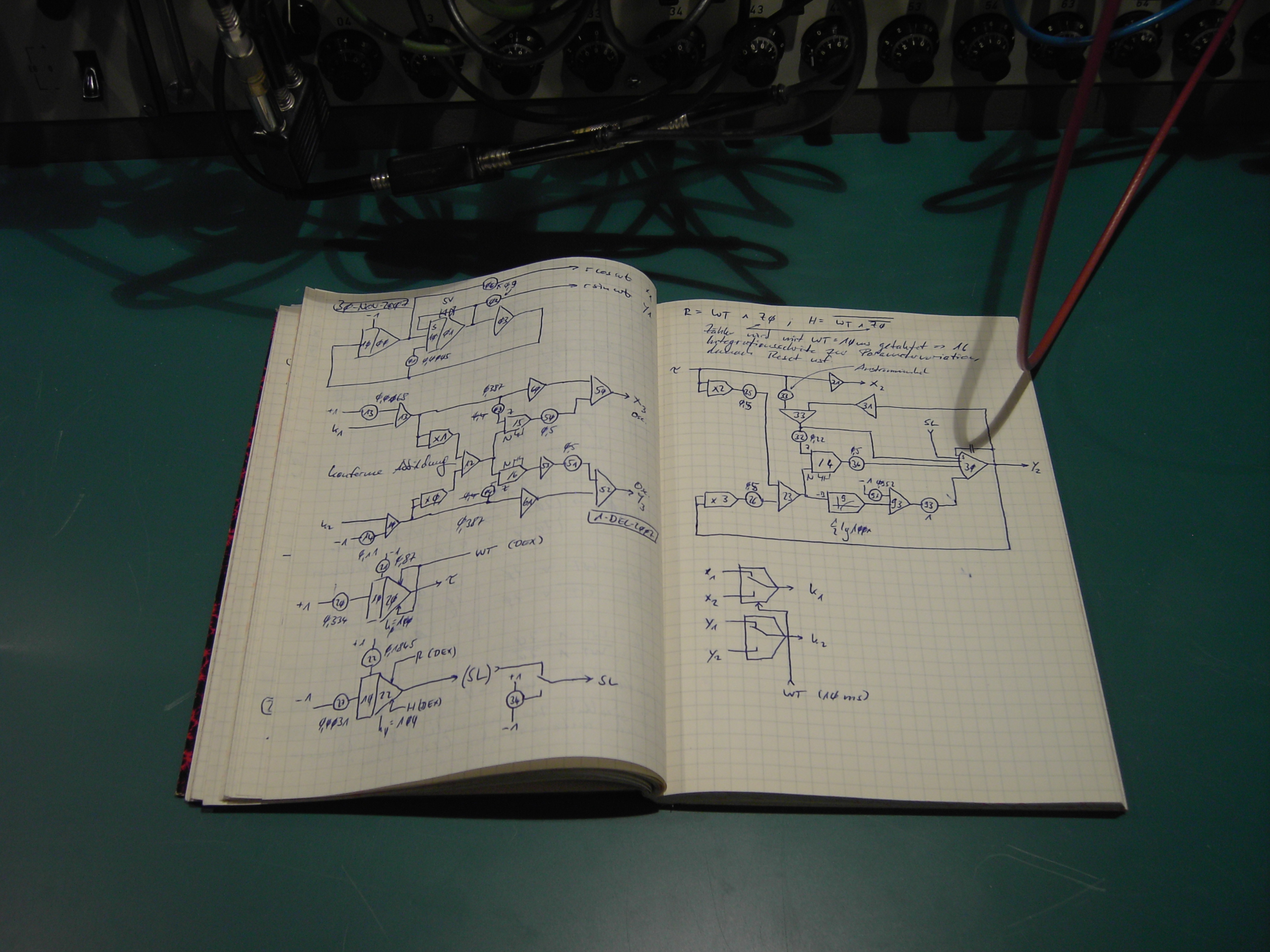
The picture below left shows a pair of pages of my sketch book which reflect part of the development of the program. The subprogram on the upper half of the left page generates the flow around the infinite rotating cylinder while the right page contains the first thoughts about the (rather simple) digital control logic for controlling the iteration process. The complete program is shown in the picture below right. It consists of seven parts:
|
|
|
|
|
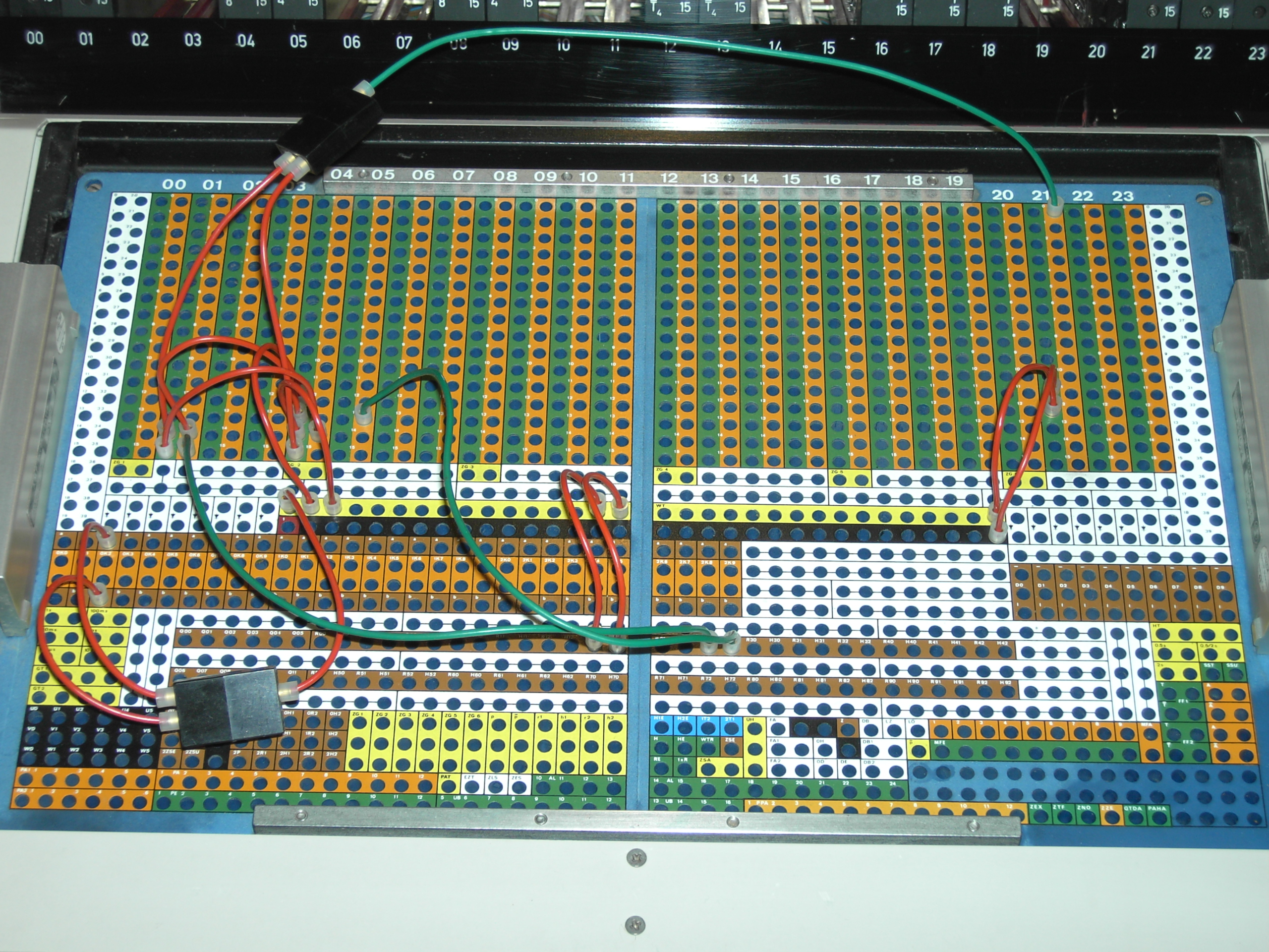
The picture on the left shows the digital control program implemeted on the DZ 772 drawer of the RA 770. The two red wires connected the the two brown jacks on the lower left control the two comparator switches with the 10 ms clock signal. The two red wires in the middle of the picture control the first repetitive operating integrator mentioned above while the rest of the program controls the iterating integrator which is necessary to generate sixteen different lines of flow in a row. |
|
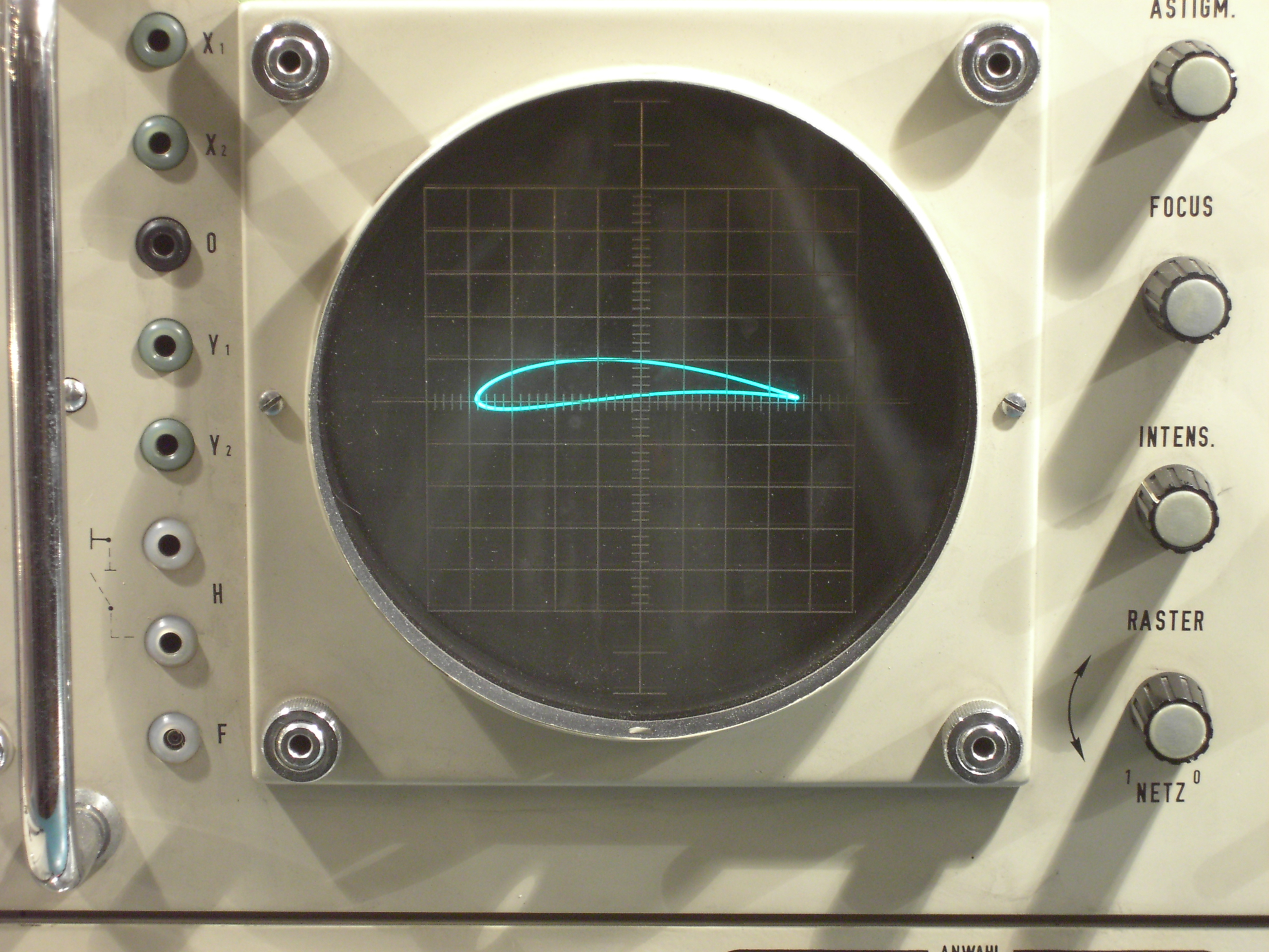
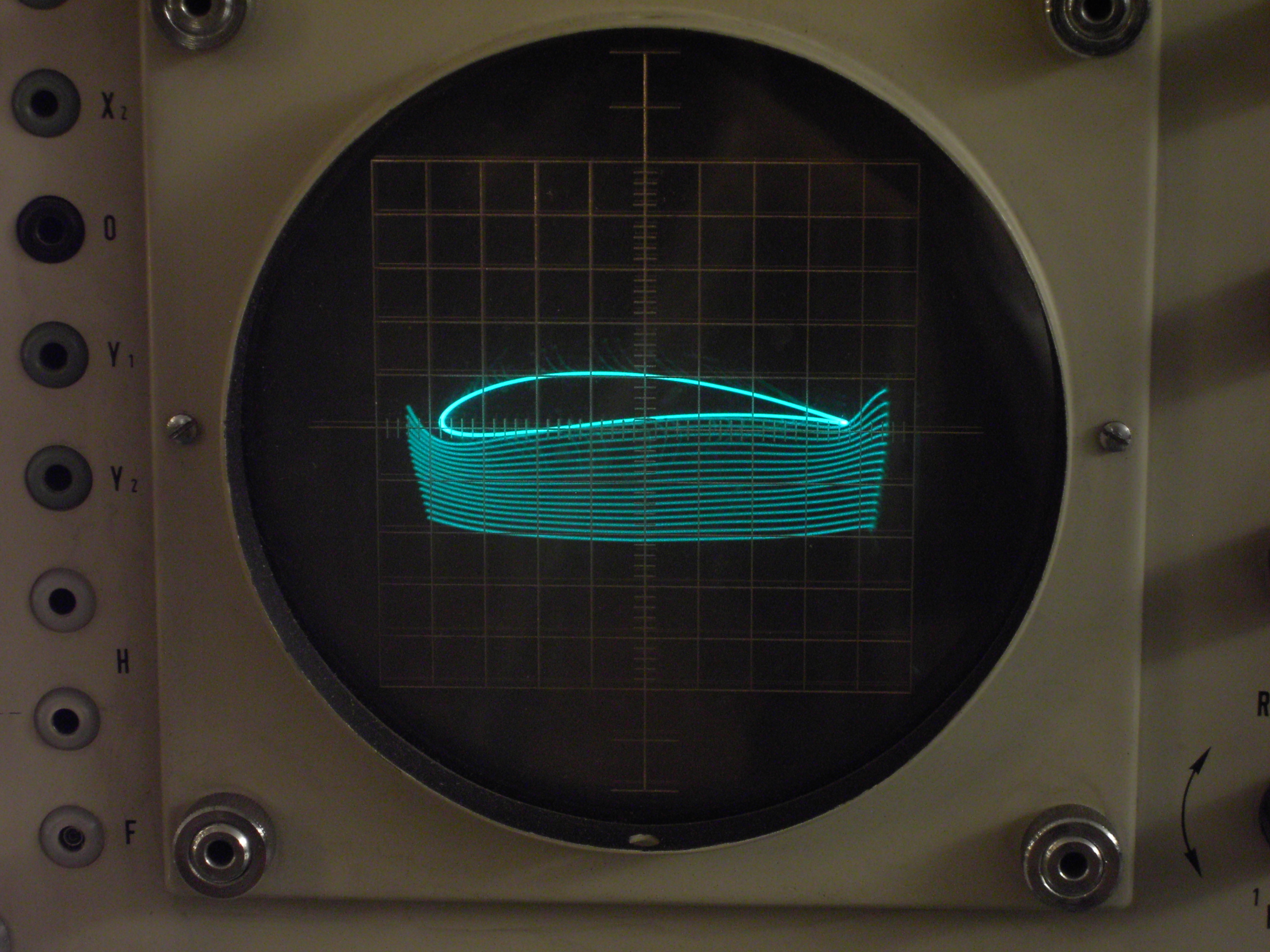
The picture on the right gives an impression of the running program with its output on the integral OMS 811 oscilloscope. |

|
|
On the left the generated Joukowski airofoil can be seen. For this picture the comparator switches have been disabled so that the conformal transformation only received the X/Y-components of the basic circle. The shape of the Joukowski airofoil can be changed (even during a computer run) by adjusting four coefficient potentiometers. |
|
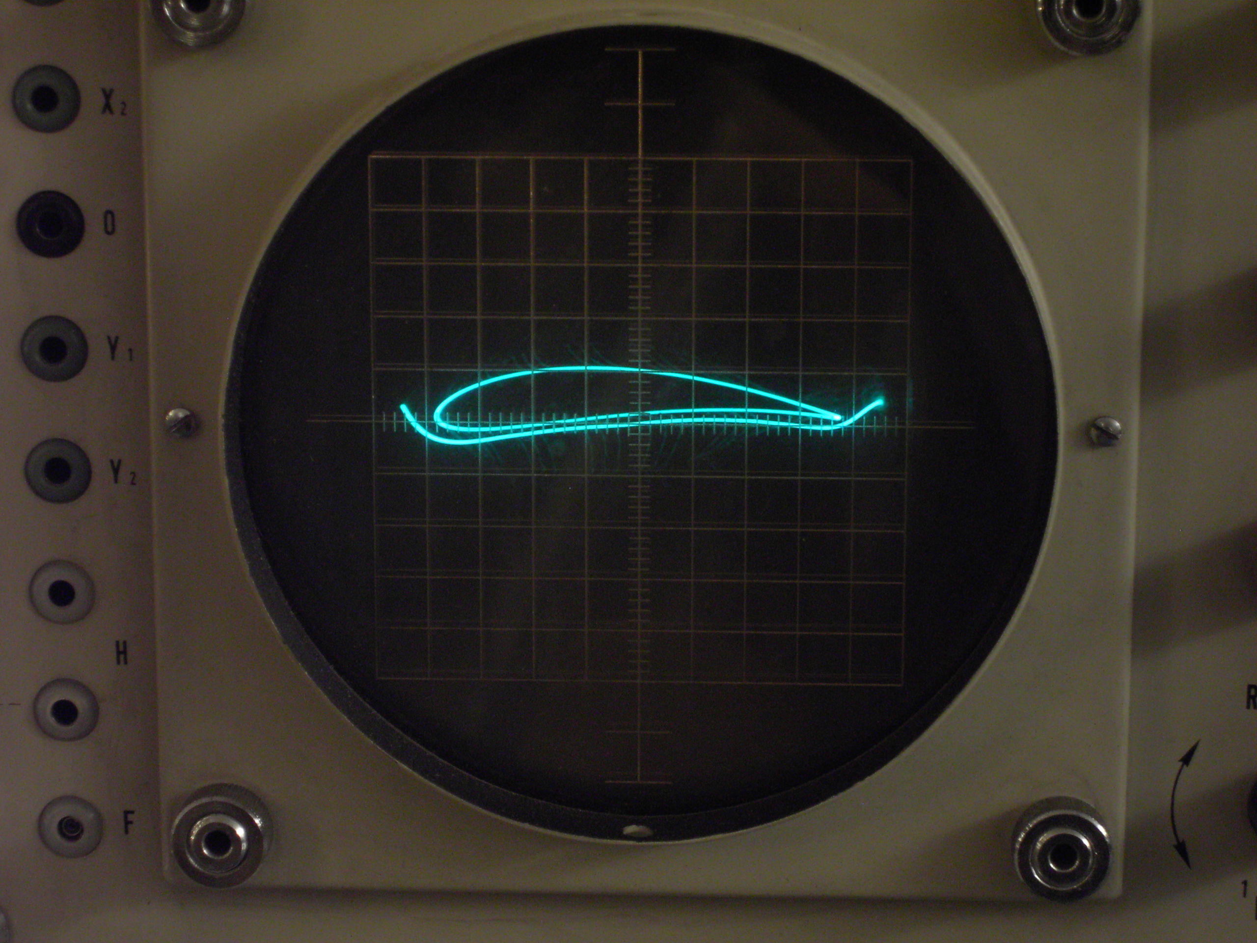
The picture on the right shows the very same profile but this time with a single (manually controlled) flow line below. The angle of attack of this particular line of flow can be seen on the left hand side so the airofoil is in a diving operation. With the aid of a coefficient potentiometer the distance between the flowline of interest and the Joukowski airofoil can be selected. |
|
|
With the aid of the iterating integrator described above it is possible to draw a family of sixteen lines of airflow around this airofoil. The airofoil is drawn in the first 5 ms half of a 10 ms clock cycle while one line of airflow is drawn in the second 5 ms part of such a clock cycle. After sixteen cycles the integrator selecting the particular line of flow will be reset etc. |
|
The two short video clips below show both modes of operation of the overall program. On the left (8 MB) a single line of flow is manipulated manually while on the right (2 MB) a family of sixteen curves is drawn under digital program control. |
|
|
|
|
Finally the short video clip on the right gives an overall impression of the Telefunken RA 770 analog computer setup to compute the Joukowski airofoil and its associated lines of airflow. |
|
|
A short video (about 5 minutes) describing this example in more detail can be seen here:
|
|
|
01-DEC-2007, 13-OCT-2010, ulmann@analogmuseum.org |
|