|
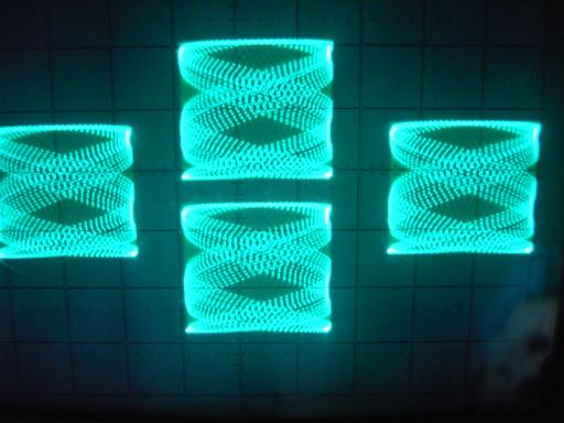
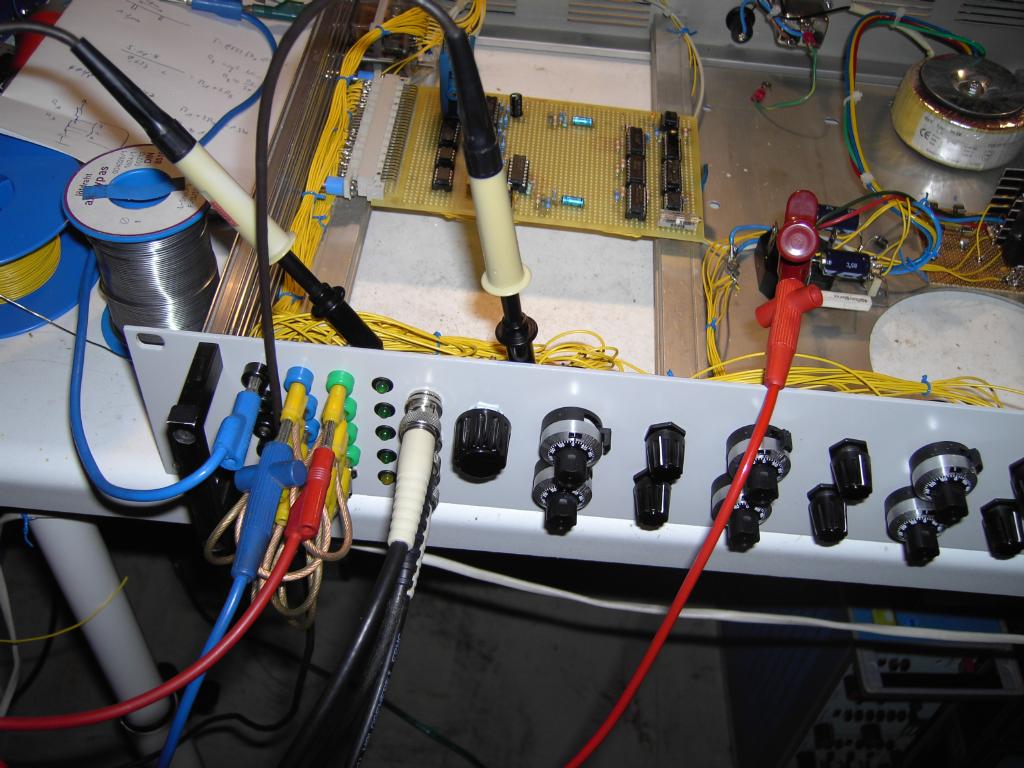
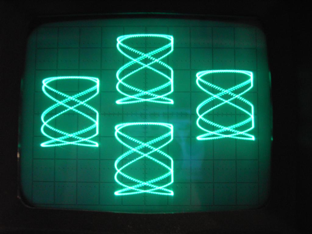
Although I have some Tektronix oscilloscopes with appropriate plug in units yielding an four channel display, I always wanted something else: A true four channel oscilloscope with four distinct X/Y inputs which would allow me not only to display four traces with a common X deflection but to draw up to four distinct figures on the screen at the same time. Something like this is very useful in conjunction with an analog computer, i.e. one can display different movong masses in a simulation at once, etc. This led to the development of such multichannel X/Y oscilloscopes like the truly wonderful Telefunken OMS 811 dual channel oscilloscope. Although I am the proud owner of such an instrument, its limitation to only two channels was a bit disappointing (currently I want to simulate a multiple spring-mass-system and display all moving masses at once to get a feeling for the forces of the system), so decided to build my own multiplexer. The front plate of the instrument can be seen later - below is a picture taken during the calibration of the multiplexer (it is a bit blurry - sorry for the bad quality - I desperately need a camera fixture for my oscilloscopes) - four Lissajous figures displayed at once (it is always the same figure since, it is some kind of a proof of concept picture):
The basic structure of the multiplexer is simple, although it was one of the more complex projects I implemented during the last years which is due to the fact of the excessive cabling necessary for all of the control elements on the front (and back) plate:
|
|
|
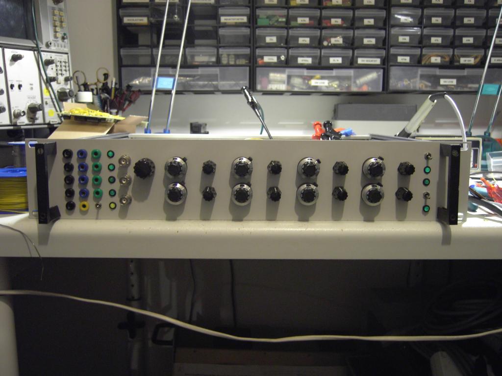
The picture on the left shows the front plate. From left to right you find the following control element groups: |
|
|
|

|

|
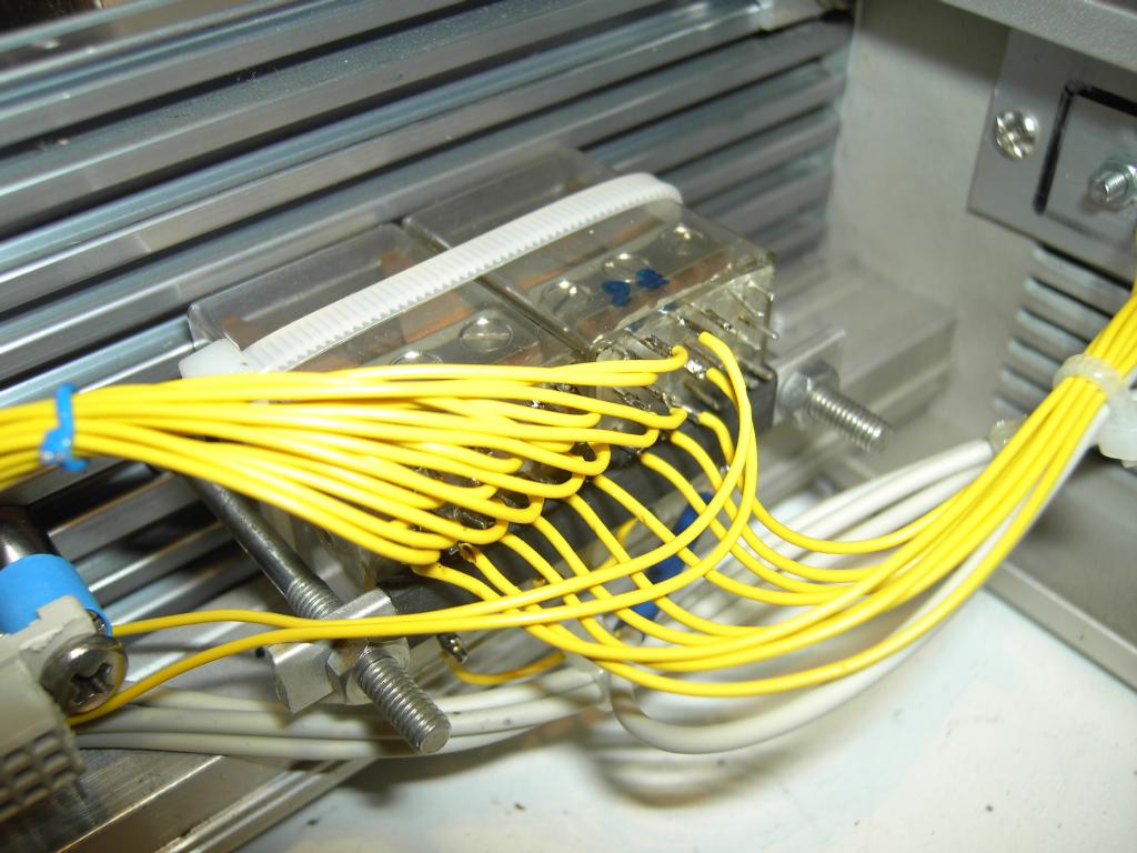
| The pictures above give an impression of the immense amount of cabling necessary to connect all of the front panel control elements to the remaining circuitry of the multiplexer. | |
|
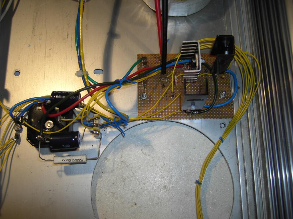
The power supply, shown on the right, is quite simple. I used a toroidal core transformer yielding 2 x 18 V with 800 mA each, followed by three integrated voltage regulators (7815, 7915 and 7805 for the blanking logic). The rectifier is way too large but was the only one I found when I started building the device. |
|
|
Shown on the left are the two input selector relays - fortunately I found two relays with six contact pairs each - eight contact pairs are needed to switch between the eight front panel X/Y input jacks and the back panel connector while another contact pair is needed to switch the blanking input between these two sources, so nine out of twelve contact pairs are utilized. |
|
|
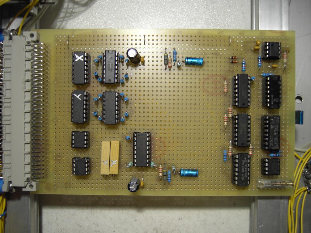
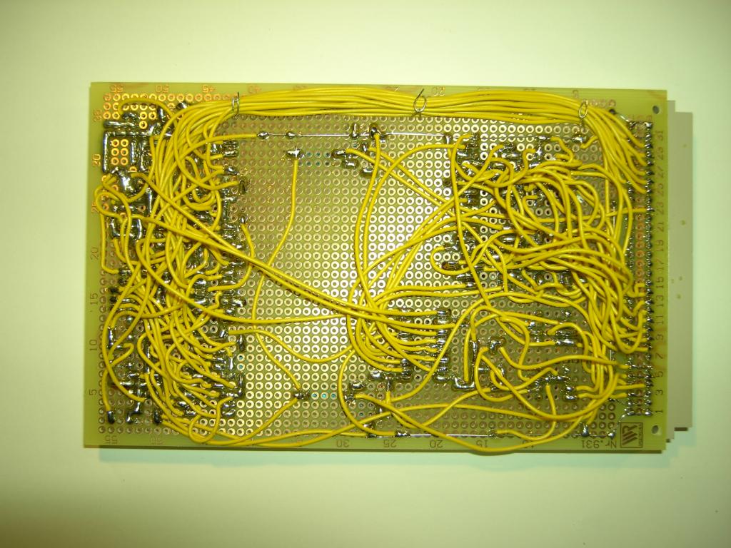
| The two pictures above show the central circuit board (component side view on the left, soldering side view on the right). Next to the VG connector are the operational amplifiers, the calibration potentiometers and the multiplexer IC itself. The other half of the board is populated with the blanking logic and associated driver circuitry. Some passive components are used to yield proper input voltages for the position setting potentiometers. | |
|
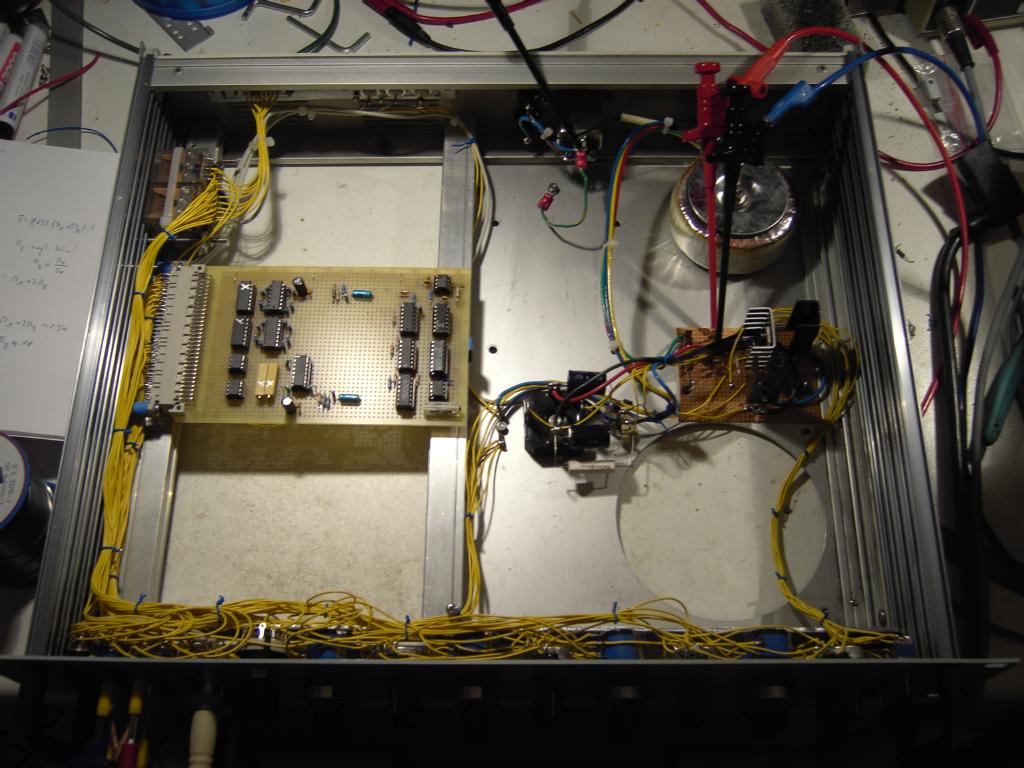
The picture on the right shows the overall multiplexer - the right half of the drawer is occupied by the (small) power supply, the left half houses the multiplexer electronics itself and the input selector relays. (The picture was taking during the test phase, thus the additional cables.) |
|
|
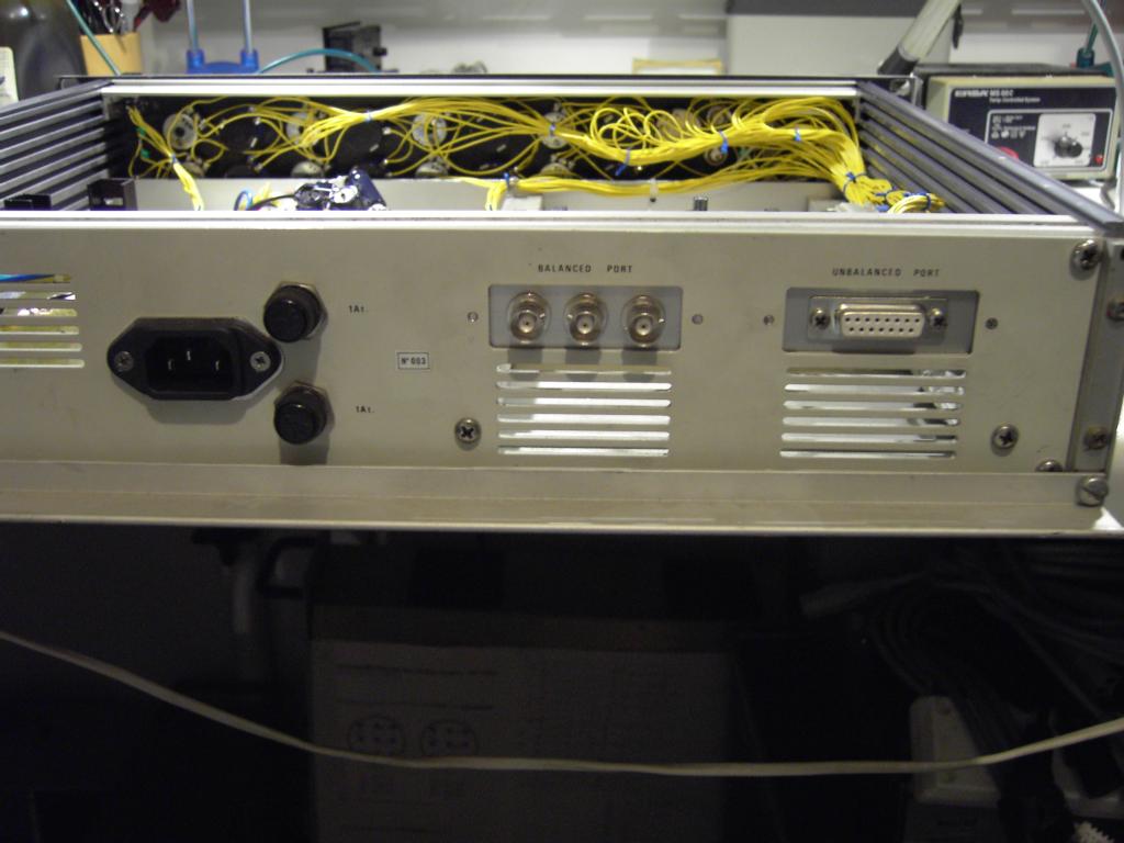
The picture on the left shows the back panel of the multiplexer. Next to the input power connector are three BNC jacks delivering the X, Y and Z signals to the oscilloscope (these are just paralleled to the corresponding jacks on the front plate) and the already mentioned 15 pin SUB-D connector. |
|
Shown on the right is a photo taking during the calibration phase. Since the MAX 355 multiplexer has a non zero resistance, the attenuation effect caused by this has to be corrected by the output operational amplifiers (OP27). To calibrate the multiplexer, I used a 1 kHz, 2 Vpp input signal for X and Y, set all attenuator potentiometers to 0.1 and adjusted the two calibration potentiometers mounted on the central circuit board for an output signal of 2 Vpp. (The attenuation by 0.1 will be compensated by the intrinsic amplification by a factor of 10.) |
|
|
|
|
|
|
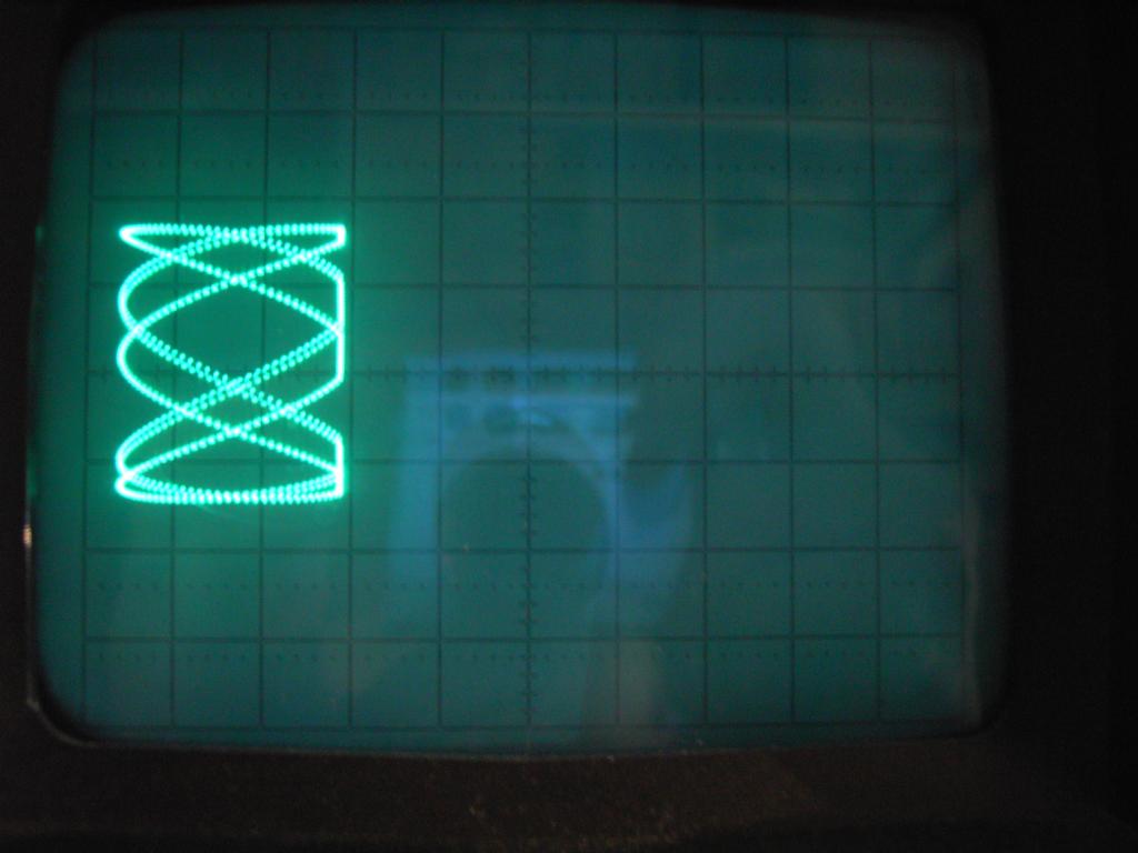
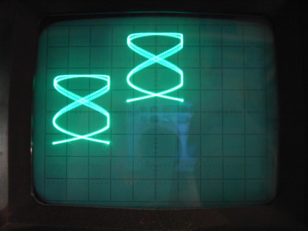
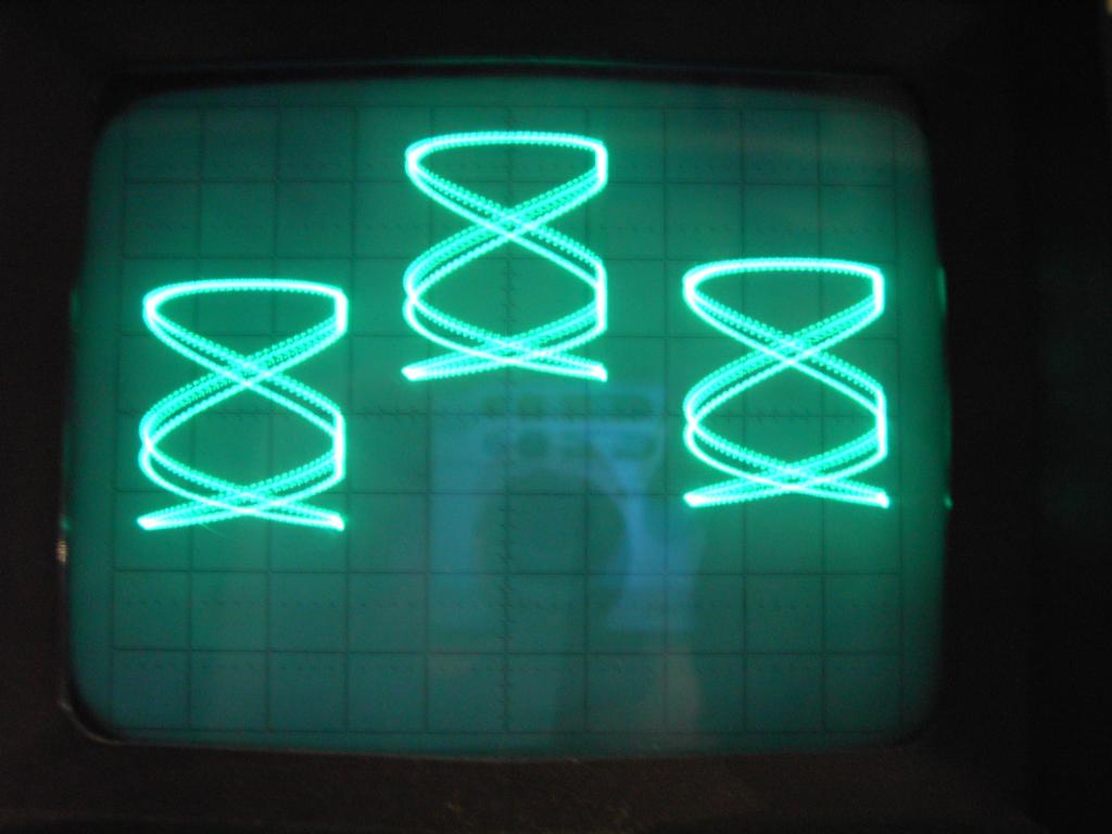
The four pictures above show the effect of the multiplexer with the channel number selector set to one, two, three and four channels respectively. Please note that the intensity of the picture does not vary with the number of channels displayed (due to a trick in the blanking logic :-) ).
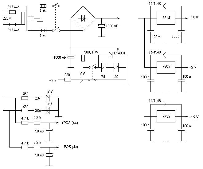
The picture above shows the power supply schematic - it bears nothing special at all, the two signal +POS and -POS are the feeder voltages for the position control potentiometers on the front plate, the two relays are the input selector relays mentioned above.
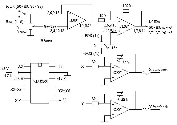
The schematic above shows the multiplexer circuitry of the device. Please note that the input section will be needed eight times, occupying four TL084 chips (and lots of wires to the front panel potentiometers). The 50k (10 turn) potentiometers in the feedback path of the OP27 operational amplifiers are used for the calibration of the multiplexer device.
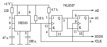
The clock generation circuitry is shown in the schematic above. An astable multivibrator made from an NE555 drives a two stage counter consisting of two JK flip flops used in a T flip flop configuration. The respective Q outputs of these flip flops are used to drive the MUX while the active low clock signal /CLK will be used for the following blanking logic.
The blanking logic shown in the schematic above generates an appropriate blanking signal to dim the oscilloscope's beam during beam movements between figures. Furthermore this Z signal can be used to suppress one to three of the maximum of four figures displayed simultaneously without having to readjust the beam intensity The operational amplifier (OP27) is used to drive the Z signal for the oscilloscope - with the aid of the potentiometer the polarity and pulse height can be adjusted to match most common oscilloscope's Z axis inputs. (For example: My HP 180C oscilloscope expects a +2 V pulse to dim the beam while ground potential at the Z input will display the beam in normal intensity.) |
|